Monday, June 27, 2011

How To Repair ACER AJ17 Monitor With Horizontal Size Problem

0 comments

Myads

How To Repair ACER AJ17 Monitor With Horizontal Size Problem

acer aj17 monitor

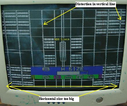
This Acer AJ17 Monitor came in with the complaint of wide screen and distortion (line swimming) across the vertical line of the display. Although you can adjust the horizontal size, you just can’t make it into smaller and the horizontal size still big and curve inward.

You could also clearly see all the vertical lines at the display have a small wave (distortion) across it. At first I thought it was caused by a defective filter capacitor at secondary side of the display but all the capacitors checked to be okay.
Since all the caps tested okay, now I fully concentrate on the horizontal size and pincushion circuit area. If there are any components shorted or faulty in this area, it will cause the display to go big (wide) and many times you can’t tune it back to normal size. From experienced, mostly the problem was the modulation diode that have shorted or a pincushion transistor that have leaked.


But both components and all the nearby circuit components checked to be okay too. Using high voltage probe to test on the anode voltage proved it to within the right range. For your information, if the holddown or safety capacitor capacitance value out it could also cause the display to turn big but of course the high voltage measured at the anode cap would be higher.

Since all the suspected components measured okay, I would then use voltage testing to locate the fault. Just before doing the voltage test, I observed that the eeprom ic is installed just beneath the picture tube. If any eeprom ic in any monitor located under the belly of the CRT, then chances are high the data would be corrupted by the discharge of the CRT.
pony prog programmer
If you repair some of the latest model of Samsung Monitor, you will understand why because the Samsung monitor had a piece of aluminum shielding to protect the microprocessor and eeprom IC from being discharge onto it.
A corrupted eeprom data could cause the micro processor to output a wrong signal to certain or all circuit. If it send a wrong signal to the DPMS circuit, then the monitor will shutdown once the power is on.

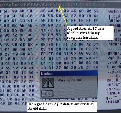
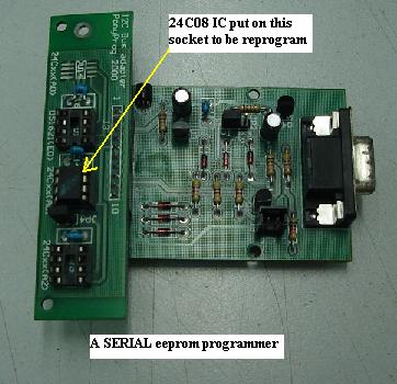
The ACER AJ17 eeprom IC part number was 24C08. I used to keep good eeprom data in my hardisk for future use just in case if there is a need to reprogram the eeprom IC. I took out the eeprom IC from the board and insert it to the center socket of the pony prog eeprom serial programmer.

I then connect it to the serial port of my computer and begin to look for the good data for this model. I do keep a lot of ACER monitor eeprom IC data.  Once I got it, I overwrite the old data with the good data.

Installing back the eeprom IC took only a while and the Monitor was switched “on”. Guess what? Not only the horizontal size now got back to normal, the distortion at the vertical lines vanished too. You better believe it that a corrupted eeprom IC could cause many weird symptoms. For some monitors, once the eeprom IC have been programmed, although the monitor work, the color may run. Some techs are good in changing the code in the data and tune to the desire colors.

In order to make the new reprogrammed eeprom data last longer, you can add a piece of shielding on top of the EEprom IC to prevent any loss data in the future. Bare in mind that, eeprom data loss not only occurs in monitor, it could happen in other electronic equipment too such as LCD Monitor, Television, UPS and etc. Whether you are repairing the ACER AJ17 or any other brand of Monitors, if you come across any weird problems that you can’t solve, try reprogramming the eeprom IC and who knows the monitor may work again. In order to do this, of course you need a serial programmer which you can easily buy one from the internet.


acer aj17 eeprom data

More Post:

Saturday, June 25, 2011

How To Build Your Own ESR Meter

0 comments

Myads

How To Build Your Own ESR Meter

Every trade has different tools of trade, for electronics the minimum you should have include:- Multimeter(Digital & Analogue), Soldering Iron/Stand, Screw driver, Side Cutter, De-soldering pump, and Soldering Wire,
These you can get them cheaply from your nearest electronics shop which I believe they are readily available. There are others which I consider very important but a bit expensive for someone who is getting started and therefore can be added later as you walk down the road of electronics repairing.
These include ESR Meter, Flyback tester, Oscilloscope among others.
In this article I am going to show you how you can make an ESR meter yourself by using readily available strip board/Vero board and get the same result as the professional assembled unit.
The reason I introduce this kit is to enable many of our followers who are starting in electronics and find it a challenge to invest in a new ESR meter.
I am sure once you add this simple but very important test equipment on your work bench you will notice an increase in the number of equipment you repair may it Television, SMPS, Monitors etc because technically speaking no electronics equipment under the sun that does not have capacitors on the circuits.
From my experience in electronics (my personal opinion) I have seen that capacitors are the major cause of problems in electronics equipment especially equipment over five years.
Capacitors fail in different ways and in most cases the meter (Digital or analogue) will not tell the truth about a faulty capacitor.
Here is where the ESR meter comes in handy as the best friend to a technician because it speaks about the true state of the capacitor at hand by measuring the equivalent series resistance (ESR) of the capacitor under test.
Equivalent series resistance (ESR) of a capacitor is considered the best parameter to know the health of an electrolytic capacitor.
The circuit is divided into two parts: The power supply and the main ESR circuit.
A)     Power supply 5 Volts DC
To assemble the power supply you need the part listed here below:  Please note that the two Polyester Capacitor no 224 and 104 are not necessary if you are using 9 volts battery and therefore can be left out of the circuit.


Assembly: Take a small piece of strip board and inert the I.C LM7805 the way it appears on the Picture below..The 9 Volts from the battery goes into Pin 1 of the i.c LM7805 and goes out from pin 3 as 5 volts dc. Pin 2 is ground and you should attach two wires on this pin (one goes to the battery negative and the other to the main circuit ground).
The 5 Volt output is taped to power the main circuit.


B)      Main ESR circuit:


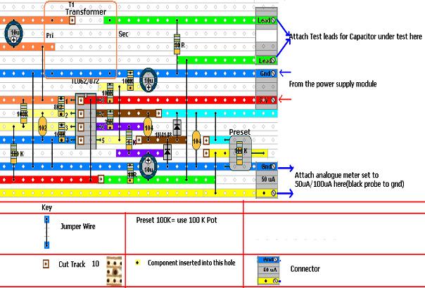
If it is possible you can print the above template with a color printer for better results and for clarity. After you finish assembling it is important you test for continuity between the 5 volts power line and the ground. It should not beep...if it beep it means there is a short on the supply line and should be sorted out before applying power. Also check for continuity between tracks to see if there is any short between any two tracks. Also make sure the Track are cut underneath according to the template and be sure to check for continuity across the Cut to see if its complete. Please note the jumper wire underneath the I.C TL062 and should be fixed first. I strongly advice to use the IC Socket 8 pin in this project and the Socket should be shouldering first for reference while installing other components.
Assembly:  Take one full piece of strip board and estimate where to insert ic socket in relation to the above circuit, in the example given here I have inserted the ic socket  pin 4 of ic TL062 at the intersection of (7 holes high from the bottom of the strip board and 10 holes from the left hand side of the strip board)
Once you install the ic socket it will guide you on installing other component in reference with this ic socket. The transformer is to be installed last. You will need to enlarge the strip board hole to inert the transformer pins.
Also note the polarity of the Electrolytic Capacitors and the diodes when installing them in the circuit. For the Capacitors I have marked the positive pole and for the diode the Stripe is the cathode (negative pole)
For the connectors use different color for the wire to avoid confussion. In the example above I have used green for Lead connector, red for 5 volts supply and blue (Black is better) for all ground and yellow connector for output (attach analogue meter set to 100uA or 50 uA)
To install the 100K Potentiometer you need to attach three wire for the three legs so that you will not have problem fixing it to the project box. Just solder the three wires as shown on the diagram to the circuit.
Component side view:

Under side view (please note the CUT) 
  
Part list for the main ESR circuit
  
Transformer should be ferrite core, you can salvage one from the dead pc power supply/ monitors/ TVs and if you find a phone charge which uses smps transformer you can use it.
  
Get a junk phone charger and salvage the Chopper transformer shown in the diagram above, usually it will have only two pins on the secondary side because in charging the phone only need one source  (5 volts) so you will use the two pin to connect to the circuit.
For the primary you will find that it will have more than two pins. Test with your meter (analogue or digital) for continuity between any two pins. The set of pins with continuity use them and for the ones without continuity just cut them off with a side cutter as shown on the diagram below. 
  
To install the Transformer:
I suggest you install the transformer and the 10 ohm resistor across the transformer out secondary pins last: this is because the transformer size and pins are not standard and therefore it will depend on what you have at hand.
 
That is why I have used two long jumpers as seen on the picture above. To install the transformer pins into the strip board you may have to enlarge the hole a bit but be sure when soldering you make connection with the track.
After you have finished assembling now its time to test if all is well. So don’t put the project into the project box yet. Take your power module and attach to the main circuit and attach your analogue meter set to 100uA/50uA. 
  
Setup
Insert the project leads into the analogue meter has shown above and power is On.
  
Short the project probes and adjust the zero adjust knob to zero mark on the analogue meter. 
If all is well up to here then you have done it and you can sit back and have some coffee for job well done.
The ESR meter is ready and should be put to do the work that it knows best…Catching those Capacitors which have been giving you headache right in circuit.
Capacitor under test:

Final product
  
In use
Use the inner scale where every box represents one (1) ohm, all electrolytic capacitors should have ESR less than 2 ohm. For any electrolytic capacitor between 2 ohms and 5 ohm please consider the working voltage of that capacitor.
For the example capacitor 4.7 uF/250 V used in CRT television to filter the RGB amplifier supply can read up to 5 ohms and still be okay. Same to capacitor 1uF/50 v also tend to read high. If you are in doubt you can always compare with a new one.
For non electrolytic capacitors they have ESR of 5 ohms and above. On my meter capacitor 0.1uF(no104) reads 5 ohms, Capacitor no.105 reads 15 ohms and capacitor 473 reads 30 ohms.
Capacitor no 224/244/474 behaves funny and the meter hand goes past the zero mark.
 
Caution:
Be sure Capacitors under test are discharged.
Good capacitors behaves as short and therefore a shorted capacitor(rare) will test like good with this meter and therefore always if you have any reason to doubt a reading use your analogue meter to confirm.
Be sure there is no capacitor in parallel with the bad one (Lift up one out of the circuit, just one leg is good enough)
Check electrolytic capacitors in-circuit- Polarity does not matter, for non electrolytic capacitors use with a pinch of salt.
If you the meter hand zero adjust is unstable after using the meter for sometimes maybe the battery is low and must be replaced.
Challenges:
As you can see I have salvaged a junk meter box for my project housing, in my market here in Kenya getting a project box is not easy and so I had to make do with whatever is available (Junk Digital meter housing)
I have also published a homemade flyback tester on my blog using Strip board and therefore if you want to build one click the link below.
With that thank you Friends
Wishing you all the best.
Humphey Kimathi
More Post:

Tuesday, June 21, 2011

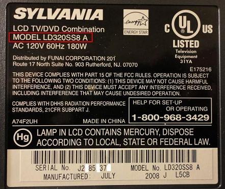
Troubleshooting And Repairing Sylvania LD320SS8 LCD TV With Shutdown Problem

0 comments

Myads

 Troubleshooting And Repairing Sylvania LD320SS8 LCD TV With Shutdown Problem

lcd tv slyvania LD320SSB 

This is a common LCD TV that we see for repair. The failure symptom is almost always that the TV will turn on for just a moment, “digital television” is displayed in the lower right corner and then the TV shuts down and goes back into standby mode.

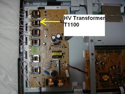
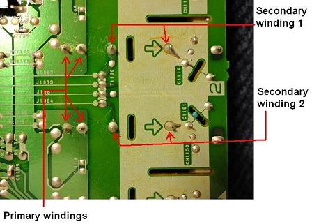
This type of failure is almost always caused by a power supply or inverter circuit failure in the majority of LCD TVs. Normally I would start by measuring output voltages from the power supply during the moment it is on to see if any are out of tolerance or missing especially the output to the inverter circuit, inspect the PCBs for solder connections with ring cracks and check the power supply secondary side filter capacitors for raised ESR and check the pico fuses and transformers on the in the inverter circuit etc.., but with this model I know that one of the HV transformers in the inverter circuit often develops an open secondary winding, typically it is  the HV transformer at location T1100. 

lcd tv high voltage transformer

The first thing I do with this model is check all the secondary windings to see if any have opened by measuring there resistance, an open winding will have an infinite resistance or if you are using a DMM you will get an O.L. (Over Limit or Open Loop) reading. Each one of the HV transformers in this model TV has 2 secondary windings. 

 lcd tv primary winding
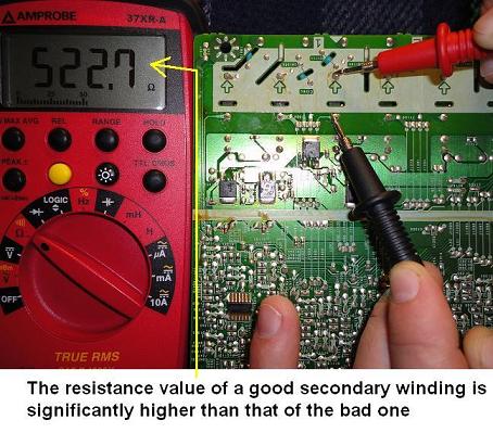
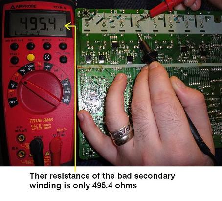
While measuring the resistance I found that none of the secondary windings had opened, but what I did notice was that one of the secondary windings had a much lower resistance that then all the others I measured. All of the secondary windings had a resistance of between 522 and 527 ohms and the suspect secondary winding had a resistance of 495.4 ohms, about 30 ohms less than the rest. This was a very good indication that this secondary winding had shorted turns. This is what's great about testing the HV transformers in most LCD TVs, being able to compare the test results of one transformer against the others as typically only one of the HV transformers will go bad and it will be easily identified when tested and compared against the others. 

lcd television transformer
lcd tv transformer


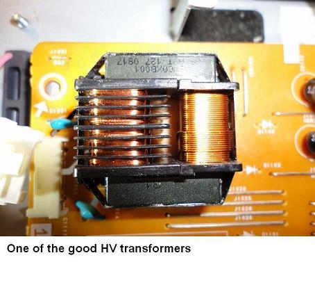
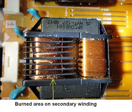
Upon closer inspection of the transformer with the shorted secondary winding the burned area of the secondary winding was noted as well, confirming without a doubt that the transformer was faulty and sure enough it was T1100, the transformer that we normally replace in this model but always for an open secondary winding but this time obviously the winding was shorted. Most likely what typically happens is the secondary coil shorts and then excess current is drawn as the resistance of the coil drops which in turn causes the coil to heat up and burn causing it to go open, but in this case the coil shorted and the TV shutdown before it had a chance to open. 

lcd television high voltage transformer
lcd television transformer

After the HV transformer was replaced with a new one, part number LTZ2PC0MS008(substitute for 3PC0XB001) the TV turned on and functioned properly once again.

The LTZ2PC0MS008 can be found at Electronica USA along with many other electronics components. 

Hopefully you all enjoy this article and special  thanks to Jestine Yong for giving me the opportunity to do a guest post this month. Best wishes to all the ERG members. As always I can be contacted by emailing me


More Post:

Wednesday, June 1, 2011

ORT-JTAG - HTC Trophy T8686 (HTC Spark) Repair Boot / Unlock / IMEI Repair & Change

0 comments

Myads

ORT - JTAG UPDATE


Description :

HTC Trophy T8686 (HTC Spark) Unbrick / Repair Dead Boot
HTC Trophy T8686 (HTC Spark) Unlock / IMEI Repair & Change

Released Stuffs :


  • HTC Trophy T8686 (HTC Spark) Repair File
  • HTC Trophy T8686 (HTC Spark) JTAG Pinout
  • HTC Trophy T8686 (HTC Spark) Instructions
  • HTC Trophy T8686 (HTC Spark) Repair Video
  • HTC Trophy T8686 (HTC Spark) Unlocking Video


Full Flashes Uploaded :


Previous Update :


ORT Team Blog :

ORT is a Real JTAGger's choice

http://www.ORT-JTAG.com
http://www.GPGORT.com

More Post:

Micro-BOX AIO 2.0.1.1 : ALCATEL UPDATE = ALL MODELS ALL PIDS

0 comments

Myads

1 JUNE 2011 - Micro-BOX AIO 2.0.1.1 : ALCATEL UPDATE

ADDED ALL LAST MODELS !

http://www.micro-box.com/images/sc/1...l_update_b.jpg

- OT-113
- OT-304
- OT-306A
- OT-361
- OT-602
- OT-602D
- OT-665
- OT-665A
- OT-809
- OT-813D
- OT-819
- OT-F121
- OT-F122
- OT-I808


WE SUPPORT ALL MODELS AND ALL PIDS ! ( 19876 PIDS )

SIMPLY THE BEST ALCATEL TOOL !


MICRO BOX V2.0 THE BEST MULTI PLATFORM UNLOCKING TOOL !

http://www.micro-box.com/alcatel_activation/

http://www.micro-box.com/images/sc/159_v.jpg


Now supported :


- OT-113
- OT-304
- OT-306A
- OT-361
- OT-602
- OT-602D
- OT-665
- OT-665A
- OT-809
- OT-813D
- OT-819
- OT-F121
- OT-F122
- OT-I808

- OT-255D
- OT-355D
- OT-505K
- OT-540
- OT-565K
- OT-710D
- OT-710K
- OT-802Y
- OT-806D
- OT-807D
- OT-808G
- OT-KR01
- OT-KR01A
- OT-MS01
- OT-MS02
- OT-Q3
- OT-T208
- OT-T218
- OT-T255
- OT-T355
- OT-900

- OT-090
- OT-103
- OT-104
- OT-105
- OT-106
- OT-108
- OT-109
- OT-112
- OT-140
- OT-150
- OT-203
- OT-203E
- OT-204
- OT-205
- OT-206
- OT-208
- OT-209
- OT-213
- OT-216
- OT-222
- OT-223
- OT-250
- OT-252
- OT-255
- OT-300
- OT-301
- OT-303
- OT-305
- OT-306
- OT-315M
- OT-355
- OT-355D
- OT-360
- OT-363
- OT-380
- OT-383
- OT-505
- OT-505K
- OT-508
- OT-543
- OT-565
- OT-565K
- OT-600
- OT-606
- OT-660
- OT-706
- OT-708
- OT-710
- OT-710K
- OT-799
- OT-800
- OT-802
- OT-803
- OT-806
- OT-807
- OT-808
- OT-813
- OT-880
- OT-AM01
- OT-F330
- OT-I606
- OT-I650
- OT-I780
- OT-I802
- OT-I880
- OT-I898
- OT-S521
- OT-S621
- OT-S626
- OT-V345
- OT-V570

- OT-103A
- OT-104A
- OT-105A
- OT-203A
- OT-208A
- OT-209A
- OT-222A
- OT-223A
- OT-255A
- OT-301A
- OT-303A
- OT-305A
- OT-355A
- OT-360A
- OT-363A
- OT-383A
- OT-508A
- OT-565A
- OT-600A
- OT-606A
- OT-660A
- OT-706A
- OT-708A
- OT-710A
- OT-799A
- OT-800A
- OT-802A
- OT-803A
- OT-806A
- OT-807A
- OT-808A
- OT-813A
- OT-880A
- OT-I650A
- OT-S521A
- OT-S626A
- OT-V570A


By IMEI only :

B331
C551
C552
C652
C700
C701
C707
C717
C750
C820
C825
E101 flip
Elle N°3
MANDARINA DUCK
MISS SIXTY
PLAYBOY
S215
S218
S220L (modem)
S319
S320
S321
S520
S853
V670
V770
vm621i
X020 (modem)
X030x (modem)
X060S (modem)
X070S (modem)
X080S (modem)
X100X (modem)
X200S (modem)
X200X (modem)
X210S (modem)
X210x (modem)
X215S (modem)
X225L (modem)
X225S (modem)
X228L (modem)

More Post:

Medusa Box 1.0.9 - lots of stuff inside!

0 comments

Myads

Version 1.0.9 – Added support for LG, Huawei, ZTE, Samsung devices!

Medusa Box v.1.0.9 Release Notes:
Added EasyRepair and Advanced modes for the following models:

  • LG KU9500
  • LG L852i
  • Samsung SPH-W2900
  • Samsung SCH-W290
  • Huawei E583c
  • ZTE MF632
  • Siemens SXG75

To resurrect these models perform the following steps:
  1. Solder JTAG cable to JTAG testpoints as explained in manual.
  2. Make sure that correct model has been selected from model list.
  3. Set Jtag speed to Auto (RTCK).
  4. Select EasyRepair mode.
  5. Press EasyRepair button and follow Wizard instructions.
  6. After operation is successfully finished verify that new device appears in PC Device Manager to make sure that it has been recovered.
  7. Desolder JTAG wires.


Download Medusa Box v.1.0.9

More Post:

HXCDongle NEW UPDATE 1.29 beta launched !!

0 comments

Myads

HXCDongle New Update Ver 1.29Beta

Whats new:
added support for Flashing HTC Glacier

Two Flash files for HTC Glacier
Glacier_TMOUS_1.14.531.1_R_Radio_12.28.60.140e_26. 03.00.04_M2_release_152476_signed.zip
Glacier_TMOUS_1.17.531.2_Radio_12.28b.60.140e_26.0 3.02.26_M_release_155771_signed.zip


NEW update already in support Area
if support area not opening then you may download from here
after .com just past this" /1915802776/HXCDongle v1.29 beta.rar "


Code:
http://www.***********.com/1915802776/HXCDongle%20v1.29%20beta.rar
all ****** just replace with e asy-share and make sure no space in easy !! as shown on picture above
Easy- share text not allowed on this forum so i also upload picture of link
also i'm uploading Flash files to E asy-Share.com !!


some users report that media fire not opening in their countries so thats why i upload it also on E asy-share.com
here is the link of that two flash files uploaded on E asy-share.com

Code:
http://www.***********.com/1915804306/Glacier_TMOUS_1.17.531.2_Radio_12.28b.60.140e_26.03.02.26_M_release_155771_signed.zip
http://www.***********.com/1915804301/Glacier_TMOUS_1.14.531.1_R_Radio_12.28.60.140e_26.03.00.04_M2_release_152476_signed.zip
all ****** just replace with e asy-share and make sure no space in easy
Happy Unlocking

More Post:

SL-Box Updates [SAMSUNG]

0 comments

Myads

Support :: SL-Box

Samsung 1.03
12.APR.2011


Galaxy Tab P1000 & P1000S Code reader added


Download Software

» SL-Box SN Reader v1.0.1.1

» SL-Box Driver Setup

» SL-Box Samsung v1.03

Samsung 1.02
09.APR.2011


Galaxy S & I9000 Code reader added

Samsung 1.01
07.APR.2011


Some bugs corrected + all drivers added in support

Samsung 1.00
04.APR.2011


A411
A412
A516
A517
A551
A706
A707
A708
A717
A727
A736
A737
A747
A811
A812
Avila
B100
B130
B200
B220
B270I
B300
B3210
B5310
B7300
Brooklyn
C140
C170
C180
C200
C210
C225
C230
C250
C250D
C250v
C260
C270
C300
C400
C425
C450
C500I
C506
C516
C520
Corby
CorbyPro
D100
D307
D347
D357
D407
D410
D415
D428
D500
D500E
D508
D520
D600
D600E
D710
D840
D900
D900i
E105
E1070
E1080
E1105
E1120
E1125
E1150
E1210S
E1310S
E1360
E1360S
E200
E210
E2100
E2100B
E2100L
E215L
E2210
E2210L
E236
E250
E250D
E250V
E300
E310
E315
E316
E317
E320
E328
E330
E340
E340E
E348
E350
E350E
E358
E360
E400
E459 E520
E530
E590
E600
E610
E620
E710
E715
E720
E730
E738
E740
E747
E750
E760
E800
E810
E820
E830
E840
E850
E860v
E880
E900
E950
F200
F210
F250
F250L
F300
F330
F338
F400
F480
F480t
F480v
F488
F490
F490v
F520
F700
F700v
G600
G800
G808
GALAXY SPIKA
Genio
Genio Slide
Genio Touch
I5700
I600
I607
I617
I700
I7500
I8000
I900v
J200
J208
J400
J600
J600E
J600i
J630
J700
J750
Kabuki
L170
L170v
L200
L310
L320
L400v
L600
L760
L760v
L766
L768
L768v
L770
L810
L810v
M110
M120
M300
M600
M610
M7500
M7600
M7600B
M8800
Monte
N700
OMNIA
OMNIA 2
OMNIA LITE
Onix
P100
P1000
P207
P310
P400
P520
P710
P720
P730 P735
P738
P777
P960
Player 5
Player One
Player Star 2
S100
S105
S200
S300
S300M
S341I
S342I
S3650
S3653
S400i
S401
S410I
S500
S500i
S501i
S5230
S5230W
S5233
S5233T
S5560
S5600
S5600V
S5620
S5750
S5750e
S720i
S720iBT
S7230
S7230E
S730i
S7330
S7350
S8300
S8300T
S8300V
Star Wififive
T456
T639
T729
T739
T809
T819
T919
Tocco Lite
U600
U700
U700b
U700v
U708
U800
U900
U908
V200
V800
V920
VE888
Wave 575
Wave 723
X100
X105
X120
X140
X150
X160
X168
X200
X426
X427
X430
X450
X460
X475
X480
X490
X500
X510
X530
X600
X610
X640
X660
X830
Z100
Z105
Z110
Z140
Z170
Z170v
Z240e
Z300
Z500
Z510
Z700
ZV-10
ZV-3
ZV6


SLBox SN Reader v1.0.1.2


Dear Customers,

if you want to access support/download zone, you need to install SL-Box driver set and SL-Box software.

Support :: SL-Box

Step 1
Run SL-Box sn reader

Step 2
Read SL-Box info and press Support button

Step 3
You can start download


More Post:

Followers


Cell Phone Repair. Copyright 2008 All Rights Reserved Revolution Two Church theme by Brian Gardner Converted into Blogger Template by Belajar Blog Bisnis Online